Tank depressurisation
Successful operation during short circuit on a 400 MVA transformer during operation Comparison of parameters recorded during transformer internal arcing event with computational simulations This...
byOmar Ahmed & Anne Goj

Successful operation during short circuit on a 400 MVA transformer during operation
Comparison of parameters recorded during transformer internal arcing event with computational simulations
This paper analyses the activation of two mechanical depressurisation devices, the transformer protector (TP), a leading example of a fast tank depressurisation technique (FTDT) and the pressure relief valve (PRV) during an internal arc on a transformer installed at the JSC RusHydro Boguchanskaya Hydro Power Plant, located in Krasnoyarsk Krai, Russia. The incident occurred on a 400 MVA three phase transformer on the 3rd May, 2013. Using all the available data, including SCADA records, dissolved gas analysis and voltage/current measurements, computational simulations were performed to study the dynamic pressure evolution and static pressure build up inside the tank. Simulation results on tank protections were analysed in the context of general arcing events. This incident demonstrates that the first dynamic pressure peak due to the arc quickly activates the FTDT, while the PRV activates with static pressure only.
Introduction
On the 3rd May, 2013, a fault occurred on a transformer installed at the JSC RusHydro Boguchanskaya Hydro Power Plant, located in Krasnoyarsk Krai, Russia. The incident occurred on phase B of the transformer T2 which is a three phase transformer manufactured on the 26th June, 2008, and in operation since the 11th May, 2012.
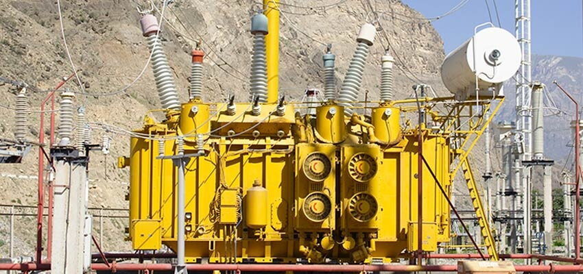
T2 has a nominal capacity of 400 MVA but was operating at 360 MVA. A schematic of the transformer can be observed in Figure 1. Transformer T2 was equipped with a TP and a PRV. During the investigation, it was observed that the transformer differential protection, the Buchholz relay, the PRV, and the TP were activated.

Figure 1: Schematic of transformer T2
Analysis of the event
SCADA
According to the SCADA data in Table 1, the transformer differential protection registered a signal at 19:08:57.110 through a warning associated with its 220 kV windings. However, the transformer protector activation signal was first registered 27 ms prior. Because the TP activation must succeed the fault, the fault is estimated to be at 19:08:57.078, roughly 5 ms prior to the TP activation. Therefore, the transformer differential protection signal was registered 32 ms after the estimated fault origin. The PRV activation signal was detected 71 ms after the estimated fault origin. Finally, the circuit breaker fully open signal was detected 97 ms after the estimated fault origin.
Due to some contradictory data between the oscillograph voltage and current measurements and the SCADA described in the ‘Short circuit energy’ section of this paper, we have doubts regarding the ability of the SCADA to timely follow all events.


