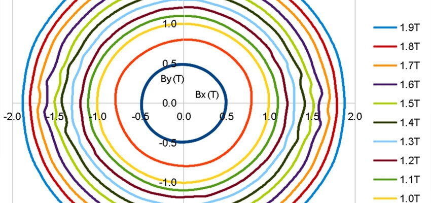
Rotational magnetisation
Abstract Rotational magnetisation is a phenomenon that occurs locally in the magnetic cores of three-limb transformers. The power loss dissipated under rotational magnetisation can be...
byDr. Stan Zurek

Abstract
Rotational magnetisation is a phenomenon that occurs locally in the magnetic cores of three-limb transformers. The power loss dissipated under rotational magnetisation can be several times higher than under usual magnetisation conditions as defined by manufacturers of the electrical steels. The phenomena were discovered over 100 years ago and have been studied since, but it is difficult to model it theoretically and apply the knowledge practically in transformer design. This article focuses on the definition and discussion of the phenomenon in order to introduce it to a wider audience of the transformer community.
Keywords: magnetic loss, iron loss, rotational loss, electrical steels, power transformers
1. Introduction
Transformer magnetic cores are built from strips of Grain-Oriented electrical steel (GO). The cores are designed so that the excitation is applied along the “easy magnetisation” direction, synonymous with manufacturing rolling direction of each of the electrical steel strips in order to optimise the performance and minimise the magnetic losses.
The cyclical magnetisation results from alternating currents in the windings – therefore such excitation is also referred to as alternating magnetisation.
Magnetisation of electrical steel can be illustrated and explained with the help of a B-H loop. Such loop also illustrates the idea of magnetic saturation, where a further increase in excitation (magnetic field strength H) yields a diminishing increase of the response (flux density B).
Measurements of magnetic properties should be carried out under well-controlled conditions, so that the results are reproducible in different laboratories [1]. A commonly used method is the so-called Epstein frame [2] on core samples, with which the measurements should be made under controlled sinusoidal B. The measurement apparatus must be capable of controlling such conditions and capturing accurately the B and H waveforms used to compose B-H loops.
It should be noted here that for electrical steels only the controlled sinusoidal B condition is used, because it is more akin to the real application where pure sinusoidal voltage leads to sinusoidal B. Of course, it is also possible to apply controlled sinusoidal H, but this condition is far less important in practice because it would require pure sinusoidal currents. B-H loops resulting from such two conditions are different and controlled sinusoidal H condition usually generates higher power loss for the same material.
Several magnetic quantities can be derived from a measured B-H loop: coercivity, permeability, and core loss (directly proportional to the area of the loop), to name but a few. The core loss, also mostly called the no-load loss, is a very important parameter for transformer design because any heat dissipated in the transformer must be taken into account in the design of the cooling system for the given transformer.
The magnetic losses are also used as the basis of classification and grading of electrical steels from which the magnetic cores are built. For example, electrical steel defined as M150-30S means electrical steel (M), whose specific loss at 1.7 T does not exceed 1.50 W/kg (150), with thickness 0.3 mm (30) of conventional grade (S) [3]. Armed with such information the designer can estimate how much loss should be dissipated in the magnetic core and adjust the design accordingly.


