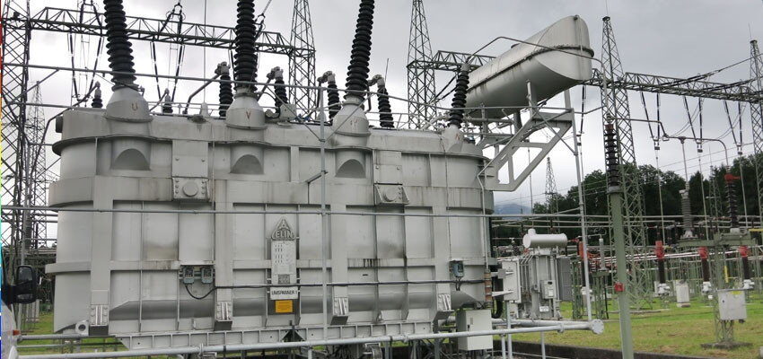
Monitoring, diagnosis and fault finding on a power transformer
Abstract An old transformer showed high concentrations of hydrogen and methane detected by the dissolved gas analysis which is usually performed at least annually as...
byMichael Krüger, Udo Ranninger, Laurentiu Viorel Badicu

Abstract
An old transformer showed high concentrations of hydrogen and methane detected by the dissolved gas analysis which is usually performed at least annually as a routine test on bigger transformers. The utility decided to install a monitoring system for measuring gasses in the oil, partial discharges according to the IEC 60270 standard and additionally in the ultra-high frequency range, capacitance and dielectric loss factor at 220 kV bushings, and for detecting transient over-voltages.
Different challenges were faced during design and installation of the diagnostic system and during the evaluation of the monitoring data. One year after installation, the monitoring system detected a strong increase of hydrogen and methane and also of partial discharges at 220 kV bushings. This initiated further diagnostic measurements. Partial discharges were detected and located. After opening the transformer the faults were identified. The damage was so serious that it was decided to scrap the transformer. This way the monitoring system could prevent a bigger damage in the substation.
Keywords: transformer, monitoring, condition diagnosis, dissolved gas analysis (DGA), partial discharge (PD) measurements, fault location, capacitance and dissipation factor monitoring
Introduction
A monitoring system was mounted on a 130 MVA transmission transformer with 230/115/48 kV because of high hydrogen and methane concentrations dissolved in the oil, detected by the Dissolved Gas Analysis (DGA). The system contained a gas sensor for four fault gasses. Additionally, Partial Discharge (PD) measurements were performed with sensors at the bushing measuring taps and with an Ultra-High Frequency (UHF) sensor inserted in the transformer tank. The monitoring system also allowed checking the state of the bushing’s insulation with absolute values of the Capacitance (C) and dielectric Dissipation Factor (DF) by utilizing nearby voltage transformers as reference. Different challenges were faced during design and installation of the diagnostic system and during the evaluation of the monitoring data.
Monitoring of the capacitance and dielectric dissipation factor of the bushings
Traditionally, the sum-of-currents method is used for bushing Capacitance (C) and dielectric Dissipation Factor (DF) measurements [1]. The current phasors of the three bushings measured at the bushing’s test taps are added to obtain the imbalance current. While the influence of differences in the bushing’s capacitances can be eliminated by calibration, the three phases of the voltage system must have exactly the same magnitude, and the angles between the phases must have exactly 120 degrees. In real cases, this is not given. Fig. 2 shows the changes of the tangent delta of a sum-of-currents system over 30 days [2]. As illustrated, the imbalance of the voltages would cause a change of tangent delta reading of more than 0.5%. The voltages of the three phases can get asymmetric by unbalanced loads or by asymmetric induction from high currents in nearby overhead lines. Oil impregnated paper bushings may have tangent delta values of 0.25%, and an increase to 0.5% could be alarming. This shows that this method is hardly suitable for accurate and reliable measurements.


