Qualitative FEM study of proximity loss reduction by various winding configurations – Part I
Abstract Skin depth and proximity effects in transformer windings are important phenomena influencing the design even at power frequencies (50-60 Hz). However, they become critically...
byStan Zurek

Abstract
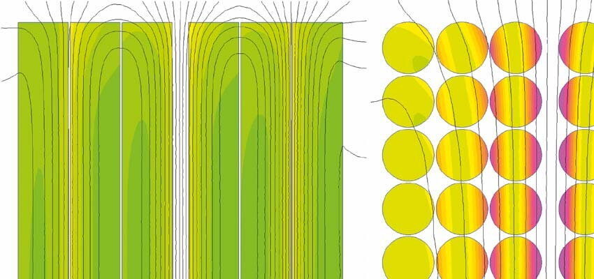
Skin depth and proximity effects in transformer windings are important phenomena influencing the design even at power frequencies (50-60 Hz). However, they become critically important at elevated frequencies, especially for high-frequency transformers, operating in switched-mode power supplies for example, at any power level. This article presents a numerical study of optimum winding configurations which can drastically reduce the proximity effects. It is possible to make transformers operating even at 1 MHz without the use of very expensive Litz wire.
Keywords: copper loss, proximity effect, proximity loss, skin effect, eddy currents, windings
1. Introduction
Efficiency of energy transformation is affected by multiple loss components occurring in transformers. These components depend on the given application, topology of conversion (conventional or switched mode), frequency of operation, energy required for forced cooling, etc.
Loss in the windings (copper loss) is a significant part of the total loss in most power transformers (e.g. as opposed to signal transformers). Electrical resistance of a given winding has an immediate impact on the total efficiency at full load due to Joule’s heating. Conductors with greater effective cross-sectional area must be used to reduce the losses and improve the efficiency.
However, transformer designers also have to take into account other, more complex phenomena, such as the skin effect. Electromagnetic wave penetrating a conducting material (copper) induces surface eddy currents which oppose the penetrating field, thus attenuating the internal electromagnetic field. The attenuation follows an exponential function and at a distance of one skin depth the field is attenuated to 37% of the surface value. Therefore, the material deeper inside the conductor carries less current and the copper is used less inefficiently.
Even at 50 Hz or 60 Hz the skin depth in copper is around 9 mm. This is partly the reason for the high-current busbars in low-voltage switchgear to be made with copper bars not thicker than 10 mm.
For higher frequencies the skin depth reduces proportionally to the square root of frequency. This becomes an important limitation for High-Frequency (HF) transformers, because the conductors cannot be thicker than around double the thickness of the skin depth in order to use the copper efficiently. For this reason many HF transformers use thin but wide copper tape in order to maintain the effective cross-sectional area of the conductor without increasing its thickness.
{READTMAGONLINE 8 70 3 1}


