Qualitative FEM study of proximity loss reduction by various winding configurations – Part II
Qualitative FEM study of proximity loss reduction by various winding configurations – Part II
byStan ZUREK

Abstract
Skin depth and proximity effects in transformer windings are important phenomena influencing the design even at power frequencies (50-60 Hz). However, they become critically important at elevated frequencies, especially for high-frequency transformers, operating in switched-mode power supplies for example, at any power level. This article presents a numerical study of optimum winding configurations which can drastically reduce the proximity effects. It is possible to make transformers operating even at 1 MHz without the use of very expensive Litz wire.
Keywords: copper loss, proximity effect, proximity loss, skin effect, eddy currents, windings
4. Further reduction of proximity loss
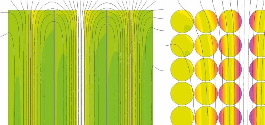
Even 1-2 interleaving (1 effective layer) produces some proximity effect, and as suggested by Dowell’s curves in Fig. 4 (in Part 1 of this paper), reduction of layers below unity would yield further decrease of proximity loss. Fig. 8a indicates how a value of 0.5 layer can be achieved, but in this particular case the improvement is overshadowed by the skin effect.
Several investigators noticed that a different kind of interleaving is beneficial. Such configurations are, for instance, disclosed in some patents [16, 17]. The concept was partially investigated by Bruce Carsten [12], and Newton Ball [18, 19], and further study and development was made by the author of this paper.
According to the proposed approach, the windings should be limited to at most a single layer each, and wound on the whole length of the core. Further improvement is obtained by ensuring that the windings are “coherent” – namely that wires do not cross, so that “the same lay, the same pitch” principle is always observed (Fig. 12).

a) b)
Figure 12. Schematic illustration of coherent (a) and non-coherent windings with wire crossings (b) [12, 13]
Otherwise, the wire crossings produce a localised non-uniformity of the field, and thus some additional proximity losses associated with it. This can be illustrated if the coherent windings are made so that both primary and secondary lie within the same layer, resulting with 0.5 effective layer, as shown in Fig. 12a, and Fig. 13a. Each wire crossing would produce a localised additional layer (Fig. 13b) and as per Dowell’s curves this would increase the losses locally. Such local losses summarised over many wire crossings would contribute to a proportional increase of total copper loss.

Figure 13. An ideal 1-1 interleave within a single layer (a) and a detrimental wire crossing (b)
#copper loss#eddy currents#Issue 9#power transformer#proximity effect#proximity loss#skin effect#Transformers Magazine#windings


