Power factor testing
Expanding the diagnostic impact of power factor testing Abstract The Narrow Band Dielectric Frequency Response (NBDFR) test method consists of a series of power...
byRobert BREAZEAL and Dinesh CHHAJER

Expanding the diagnostic impact of power factor testing
Abstract
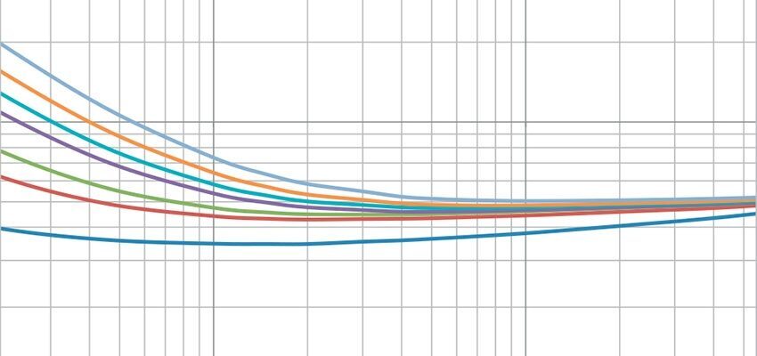
The Narrow Band Dielectric Frequency Response (NBDFR) test method consists of a series of power factor measurements ranging from 1 to 1000 Hz. This aggregate of the CHL (primary to secondary) measurements constitutes the dielectric response of the test specimen. The subsequent evaluation consists of a geometric analysis of a plot where the measured power factors and corresponding frequencies are graphed. As an insulation system ages, the response migrates towards the high frequency end of the plot. When the frequency corresponding to the lowest magnitude within the response (the trough) is used as a reference point, the movement of the response may be quantified; enabling the transformer may be classified in terms of condition.
Keywords: power factor; insulation; oil; dielectric response; transformer
1 Unlocking the secrets of the NBDFR trace
The bandwidth from 10-100 Hz is dominated by the condition of the cellulose components of the insulation system. The negligible conductive losses, combined with dense winding design, results in a trough location at 15 Hz. The magnitude at line frequency should be noted, as this is the conventional parameter used in condition assessment. Although it is not a definitive characteristic, the slope at line frequency should also be noted, as this, along with power factor at lower frequencies, will assist in evaluating the insulation condition. The bandwidth from 100-1000 Hz is influenced by static charge polarization losses, most notably from 400 to 1000 Hz. As this unit begins to age, an increase in pitch is observed from 400-1000 Hz as polarization losses become visible. As degradation progresses, the entire response moves towards the high frequency end of the graph. The elevated tail will be pushed past 1000 Hz, which will create the illusion that the high frequency tail is flattening out.
2 Trough location: The magic key to condition assessment
A prevailing interpretation states that, if the response slope is positive at line frequency and at 20 ⁰C, the insulation system is in acceptable condition [1]. This paradigm would seemingly provide a pass/fail acceptance criteria for condition assessment. This, however, is an oversimplification, as slope is a result of trough location. As the insulation (cellulose and oil) degrade, increasing conductive losses cause the response to migrate towards the high frequency side of the plot. The trough moves proportionally as the response migrates; therefore, the trough functions as a marker by which the degree of movement may be observed. By monitoring the frequency at which the trough is located, insulation condition may be progressively and incrementally tracked. As a robust data base is established for a particular make and model of a transformer, condition classifications may be assigned based on trough frequency.[2]


