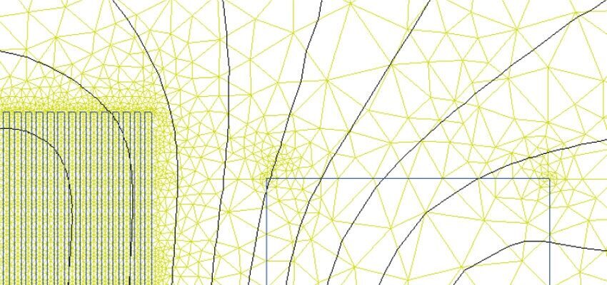
Losses in foil winding
Power losses model of a foil winding Abstract A semi-analytical method for calculating foil winding power losses is presented in the article. The short-circuit losses...
byMislav TRBUŠIC and Igor LUGARIC

Power losses model of a foil winding
Abstract
A semi-analytical method for calculating foil winding power losses is presented in the article. The short-circuit losses of foil type windings are somehow greater in comparison to the other types of windings consisting of rectangular conductors or magnet wires. The main reason for higher losses is related to eddy currents induced by the magnetic field passing through the foil surface. Namely, the eddy currents in the foil are developed through a large surface area, which gives rise to current density. However, the proposed method is based on the stray magnetic field distribution along the foil winding, from which the eddy currents are evaluated. The novelty of the method is introduced through a so-called “residual flux” which results from asymmetric field distribution along the foil and contributes strongly to power losses.
Keywords: foil winding, loss calculation, rectifier transformer, FEM
- Introduction
In transformer units with a nominal power rate up to a few MVA and relatively low voltage applications below 3 kV, the foil type of winding is generally applied to the low-voltage side. The typical applications for this type of winding are small distribution and rectifier transformers. The main advantage of the foil winding over the disc or a single layer type is its geometrical feature, since, usually, the height of the foil is much greater than its thickness, which gives a desirable conductor cross section, as well as simplifies the winding process of the coil. On the other hand, due to the large surface area of the foil, the stray magnetic field induces eddy currents which produce significant additional losses, and can reach as much as 70 % of the winding DC losses. However, the addressed topic is, mathematically and computationally, a rather comprehensive task that requires a numerical approach, but still, even with the most extensively used method in the computational electromagnetics, the Finite Element Method (FEM), issues arise when the thick objects such as foil windings are involved in the analysis. For this reason, the semi analytical method of the additional losses’ calculation is presented in the article. Here, the magnetic field in the transformer’s window (the leakage or stray field) is computed by the FEM, and the following losses related to the field are evaluated through the analytical expression.


