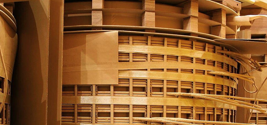
Classic Power Transformer Windings
The separate windings of every phase and every voltage level are assembled together onto a magnetic core. This core is typically made of cold rolled...
byJean Sanchez

The separate windings of every phase and every voltage level are assembled together onto a magnetic core. This core is typically made of cold rolled grain oriented steel, which is a highly magnetically permeable material, and highly facilitates mutual induction. The flux generated by the primary windings, which are connected to an electrical source, links with the secondary windings, which are connected to the load.
The main flux for the no-load state passes through the core, the flux generated by the load is mainly passing into the space between the HV and the LV winding of every phase. This space between HV and LV (and MV if existing) windings is the main parameter for the short circuit impedance, which is a main characteristic of any power transformer.
Each winding, having a given number of turns, the voltage ratio at no-load condition of the transformer (> 1), is directly proportional to the turns ratio (number of HV turns on number of LV turns). To minimise Eddy Current losses in the windings the conductors are wound almost always in parallel to build one electrical turn.
The line lead could be mostly taken out at the centre or the top of the coil, according to manufacturer experience.
Power transformer windings, mainly in contrast with distribution transformers, are still manually manufactured, as they could be quite massive, complex and should withstand very high stresses of over-voltage [3] and short-circuit current [4], and evacuate some important amount of energy losses.
Consequently over decades, only a few types of windings have remained used by most of the power transformer manufacturers, and those general power transformer windings are presented in this paper.
It should be understood and remembered that every power transformer manufacturer and almost every transformer factory has its own experience on winding design and manufacturing, which could be detailed infinitely. Those details are generally not communicated by the manufacturer as any one of those details should basically lead to an improvement of withstand capability of over-voltage, over-current, heat transfer capability or ease of manufacturing. The winding details could be quite strategic and make a technically significant difference between the manufacturers.
In the figures presented in this paper, the numbers are in a continuous sequence of turns. Those turns can be interleaved for design purpose, mainly to better withstand impulse test by increasing some internal capacitance.
Continuous disc windings
Continuous disc winding might be the most used power transformer winding design worldwide as it is a robust winding suitable for most of the transformers. It could be seen as multiple “radial stages” of turns. When one stage is completed, a crossover is made to start the next axial stage (as shown in the figure below), and so on, along the height of the winding.


