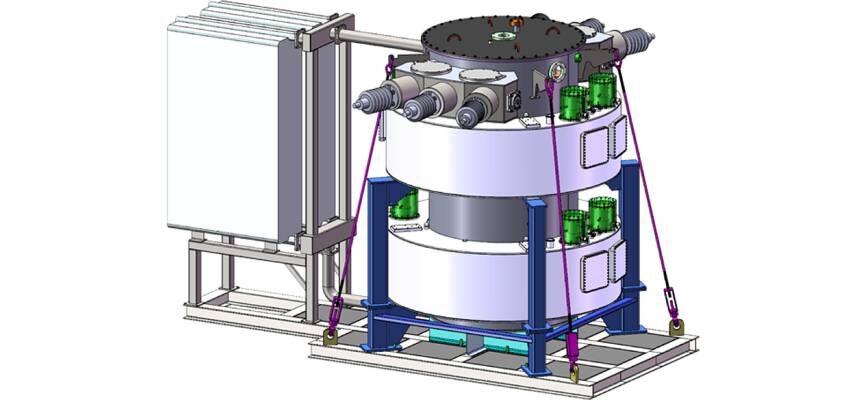
Application of magnesium diboride in saturated core fault current limiters
A fault current limiter must be able to change impedance autonomously, without active sensing or actuation systems that might be prone to failure.
byDavid Klaus and Christian-Eric Bruzek

- Introduction
A fault current limiter must be able to change impedance autonomously, without active sensing or actuation systems that might be prone to failure. This is because FCLs are installed in series connection with other network components that have limited ability to withstand the passage of fault-current, or in the case of switchgear, maximum fault making and breaking capacities. Two broad categories of FCL using superconductivity, generally referred to as resistive and inductive, have been developed. They operate in very different ways.
- Superconducting FCL types
2.1 Resistive FCL
In a resistive limiter, load current feeding customers is passed through a superconducting circuit which is dimensioned to revert to a normally conducting state (quench) if the current exceeds a certain level. A series circuit breaker operated by a rapid and reliable local protection system must interrupt the current through the FCL to protect the quenched superconducting circuit from overheating and allow for the said circuit to cool to below its critical temperature, and for the FCL to be reconnected. Cooling down may require a few minutes and to maintain the continuity of power distribution during the temperature recovery operation, conventional reactors may be connected in parallel with the superconducting circuit. Where high-temperature superconducting material is used (typically Bi2212, Bi2223 or YBCO, all of which have critical temperatures of around 90 K), cooling may be achieved by immersing the HTS circuit in liquid nitrogen. Today YBCO tapes having a high resistance in the normal state are used in state-of-the-art resistive FCLs.
2.2 Inductive FCL
In an inductive FCL, the fault limiting impedance takes the form of inductive reactance, which can be inserted into the load current path in a number of ways, including using a resistive limiter connected in parallel with a conventional series reactor. The technology described here is inductive, but no load-current flows in the superconducting circuit, which is only required to carry dc current.


