Superconducting traction transformer
As a result, the 300 kW oil cooling system takes a large share of the weight and space. The whole system weighs just under 6tons.
byWenjuan Song et al.

High-speed rail provides an alternative to short-haul air travel with the potential for significantly reducing transportation CO2 emissions [1]. China’s high-speed rail network has developed extremely rapidly in a little over a decade, now comprising over half of the global track length and carrying more than twice as many passengers as its domestic airlines [2].
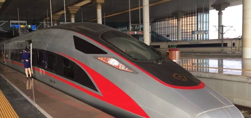
The traction transformer is a key component of high-speed trains. Fig. 1 shows the layout of the transformer system for the Chinese Fuxing train, where one 6.5 MVA transformer supplies power to four drive units. With windings operating at a high current density to optimize system weight, the transformer is only 95 % efficient. As a result, the 300 kW oil cooling system takes a large share of the weight and space. The whole system weighs just under 6tons.
These characteristics are typical of conventional traction transformers. There is also a significant fire hazard. These deficiencies, particularly weight, become more constraining with increasing train speed. High temperature superconducting (HTS) transformers, in contrast, offer high power density, high efficiency, and much lower fire risk thanks to their liquid nitrogen dielectric.
There have been two earlier projects aimed at demonstrating HTS traction transformers. In 2003, Siemens produced a 1 MVA traction transformer notable for the first use of HTS Roebel cable in the transformer windings [3], and about the same time, the Japan Railway Technical Research Institute developed a 4 MVA HTS transformer [4]. Both of these projects used so-called first-generation wire, a bismuth strontium calcium cuprate superconducting composition. This wire has since been largely superseded for transformer applications by second-generation wire, based on thin-film yttrium barium cuprate, which exhibits much lower loss in the parallel AC magnetic fields that pervade transformer windings.
Both transformers used liquid nitrogen as both dielectric and coolant. The Japan Rail transformer operated at 66 K, 11 K below the boiling point of liquid nitrogen. It had 7 kW loss at rated power and required a cryocooler that was bigger and heavier than the transformer itself. The efficiency of the Siemens transformer was not reported.


